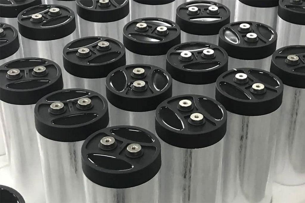
PTFE Dielectric Films: An Overview for Automotive Capacitors

Polytetrafluoroethylene (PTFE), widely recognized by the DuPont trademark Teflon, stands out among dielectric materials for its exceptional thermal, electrical, and chemical performance.
In automotive applications, particularly in electric and hybrid vehicles, PTFE dielectric films are increasingly valued in capacitors for their exceptional combination of properties.
Thermal Endurance & Stability
One of PTFE’s most compelling advantages is its remarkable temperature tolerance,capacitors employing PTFE dielectrics can operate reliably up to 200 °C, and in some cases even 260 °C when derating is applied. These thermal limits surpass those of other polymer dielectrics such as polypropylene (max ~125–150 °C) and polycarbonate (max ~125 °C).
In automotive contexts—where capacitors may be situated near hot power electronics or propulsion systems, this resilience is invaluable for ensuring long-term reliability.
Low Losses & High-Frequency Performance
PTFE features an extremely low dissipation factor (DF), typically in the range of <2 × 10⁻⁴, combined with a low dielectric constant around 2.0–2.2. This means PTFE capacitors exhibit minimal energy loss (heat generation) and excellent performance across broad frequency ranges.
For high-power inverters, onboard chargers, and RF systems in EVs, maintaining efficiency and signal integrity is key, traits where PTFE excels.
High Dielectric Strength vs. Physical Trade-offs
PTFE films boast high dielectric strength—typical values span 60 to 100 kV/mm. This enables capacitors to be designed for high-voltage environments such as 800 V battery stacks or powertrain systems. Still, a trade-off exists: the minimum thickness of PTFE dielectric films is typically around 5.5 µm, roughly double that of polypropylene (PP). Thicker dielectrics result in larger capacitors, which can pose packaging challenges, especially in compact automotive modules.
Enhanced Energy Density & Emerging Uses
Recent advances have pushed PTFE toward higher energy storage capabilities. For instance, surface flattening treatments—like epoxy coating—have achieved breakdown strengths up to 555 kV/mm, energy density of 3.58 J/cm³, and 98–99% discharge efficiency, even at elevated temperatures (~150 °C).
Moreover, according to market research covering the new energy vehicle sector, PTFE (and hybrid films including PTFE) can offer energy densities > 3 J/cm³, compared to around 1.5 J/cm³ for standard PP films. This has facilitated applications such as 800 V battery systems in luxury EVs, enabling up to 12% faster charging, with acceptable cost premiums (~40%).
Mechanical & Manufacturing Challenges
A historical obstacle for PTFE in capacitors has been its poor metallization adhesion and low mechanical tensile strength, especially in cast or skived films, which can stretch or neck down during winding. However, innovations—such as densified expanded PTFE films with tensile strengths exceeding 10,000 psi—have allowed reliable manufacturing of high-temperature capacitors functioning up to 250 °C. Nonetheless, metallizing PTFE remains more complex compared to other films like polypropylene.
Additionally, surface treatments (sodium etching, plasma etching, ion beams) improve adhesion properties by increasing surface energy or roughness—but add manufacturing complexity and cost.
Cost, Size, and Trade-offs in Automotive Design
PTFE’s superior properties don’t come cheap. Its higher material and production costs, combined with lower capacitance per volume (due to low εᵣ and thicker films), mean PTFE capacitors are bulkier and more expensive than PP or PET alternatives.
Automotive engineers must therefore consider whether performance benefits (high-temperature tolerance, low loss, high voltage) justify the trade-offs. In high-end EVs—or systems exposed to harsh thermal environments—PTFE may offer net benefits, such as improved charging speed or reliability margin, justifying a ~40% cost premium.
Summary Table: PTFE vs. Other Dielectrics
| Property | PTFE (Teflon) | Polypropylene (PP) | Polyester (PET) |
|---|---|---|---|
| Dielectric Constant (εᵣ) | ~2.0–2.2 | ~2.2–2.3 | ~3.3–3.8 |
| Dissipation Factor (DF) | Ultra-low (< 2×10⁻⁴) | Low–medium | Higher (~0.002–0.005) |
| Max Temp | 200–260 °C | ~125–150 °C | ~85 °C |
| Dielectric Strength | High (~60–100 kV/mm) | Very high (~500–700 V/µm) | Moderate (~200–300 V/µm) |
| Film Thickness | ~5.5 µm (min) | ~1.9–3.0 µm | ~0.7–0.9 µm |
| Cost | High | Moderate | Low–moderate |
| Size Efficiency | Low (bulkier) | Moderate | High (compact) |


